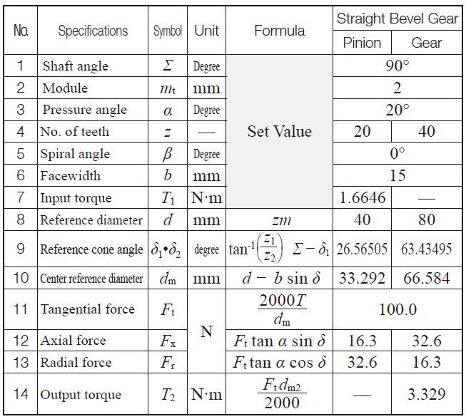
The key items in profile shifted gears are the operating(working) pitch diameters (d w) and the working (operating) pressure angle (α w). In this case,it will be necessary to resort to profile shifting or to employ helical gears to obtain as near a transmission ratioas possible.įigure 4.2 shows the meshing of a pair of profile shifted gears. Note, that the number of teeth will probably not be integer values when using the formulas in Table 4.2. of Teeth z 1 + z 2 2a / m 36 5 Number of Teeth z z 1 + z 2 / i + 1 i (z 1 + z 2) / i + 1 16 20 Item Symbol Formula Example Pinion (1) Gear (2) 1 Module m Set Value 3 2 Center Distance a 54.000 3 Speed Ratio i 1.25 4 Sum of No. The calculation formulas are in Table 4.1.įig. The meshing of standard spur gears means the reference circlesof two gears contact and roll with each other.

The standard spur gear is a non-profile-shifted spur gear.įigure 4.1 shows the meshing of standard spur gears. This section introduces calculation methods of standard spur gears, profileshifted spur gears, and linear racks. The calculations for spur gears are also simple and they are used as the basisfor the calculations for other types of gears. Spur Gears are the simplest type of gear. Tooth dimensionssuch as root diameter or tooth depth are considered when gear cutting. Tip diameter) are necessary for processing the gear blanks.


This section introduces the dimension calculations for spur gears, helical gears, gear rack, bevel gears, screw gears, and worm gear pairs. Gear dimensions are determined in accordance with their specifications, such as Module (m), Number of teeth (z), Pressureangle (α), and Profile shift coefficient (x).


 0 kommentar(er)
